13 Results
View results:
Sort by:

CFD calculations are in general very complex. An accurate calculation of wind flow around complicated structures is very demanding on time and computational costs. In many civil engineering applications, high accuracy is not needed and our CFD program RWIND 2 enables in such cases to simplify the model of a structure and reduce the costs significantly. In this article, some questions about the simplification are answered.

The events of recent years remind us of the importance of earthquake engineering in seismic regions. For you as an engineer, the design of structures in earthquake-prone areas is a constant trade-off between economic efficiency – the financial possibilities – and structural safety. If a collapse is inevitable, engineers must estimate how it will affect the structure. This article aims to provide you with an option on how to perform this estimation.

The size of the computational domain (wind tunnel size) is an important aspect of wind simulation that has a significant impact on the accuracy as well as the cost of CFD simulations.
This article shows you how to estimate CO2 emissions in RFEM 6/RSTAB 9.
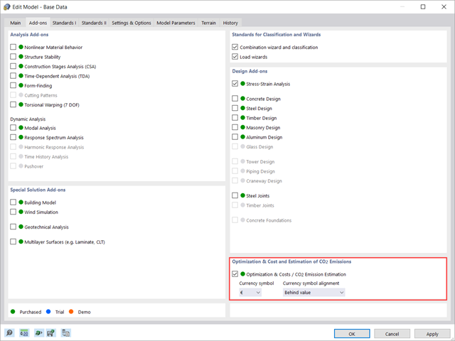
This article shows you how to use the add-on Optimization & Costs / CO2 Emission Estimation to estimate the model costs. Furthermore, it shows you how to optimize parameters based on minimum cost when working with parameterized models and blocks.

The shear force resistance VRd,c without computational shear force reinforcement according to 6.2.2 of EN 1992-1-1 [1] or 10.3.3 of DIN 1045-1 [2] is calculated depending on the longitudinal reinforcement ratio. If the required longitudinal reinforcement from the bending design is used for the calculation of VRd,c, this leads to an underestimation of the shear force resistance without shear reinforcement in the vicinity of the hinged end supports. In contrast to the shear force, the required bending reinforcement decreases in the direction of the support. Furthermore, the actually inserted longitudinal reinforcement usually deviates significantly from the required bending reinforcement in the end support area (for example, in the case of non-staggered beam reinforcement).

To cover the required transverse reinforcement, RF‑CONCRETE Members and CONCRETE determine the most cost-efficient transverse reinforcement as a reinforcement proposal in accordance with the predefined stirrup diameter.

Fin plate connections are a popular form of pinned steel connection and are commonly used for secondary beams in steel structures. They can be used easily in beam structures arranged on the top edge (for example, working platforms). Manufacturing expenditures in the workshop as well as the onsite assembly costs are normally manageable. The design seems to be completed easily and quickly, but it has to be put into perspective to a certain extent in the following text. Moreover, this connection type is basically possible as a pinned beam-to-beam or pinned beam-to-column connection; the former case is the more common one in design practice.
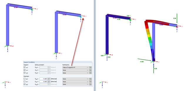
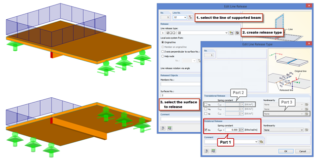
In practice, an engineer often faces the task of representing the support conditions as close to the reality as possible in order to be able to analyze the deformations and internal forces of the structure subjected to their influence and to enable construction that is as cost efficient as possible. RFEM and RSTAB provide numerous options for defining nonlinear nodal supports. This second part describes the options for creating a nonlinear support for a restraint and provides a simple example. For a better understanding, the result is always compared to a linearly defined support.
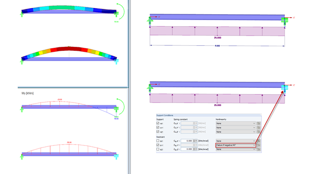
In practice, an engineer often faces the task of representing the support conditions as close to the reality as possible in order to be able to analyze the deformations and internal forces of the structure subjected to their influence and to enable construction that is as cost-effective as possible. RFEM and RSTAB provide numerous options for defining nonlinear nodal supports. The first section of my article describes the options for creating a nonlinear free support and provides a simple example. For a better understanding, the result is always compared to a linearly defined support.
![System and Loading According to [1]](/en/webimage/009455/2418877/01-en-png.png?mw=640&hash=c76563b459152b19c98197ea6ba342be89d9a5bc)
The product range of Dlubal Software contains various modules for design of steel and timber connections. The RF-/JOINTS Steel – Column Base add-on module allows you to analyse footings of hinged or restrained steel column bases. The fastener selection, foundation geometry, and material quality are crucial for the cost-effective and safe design of the column base.
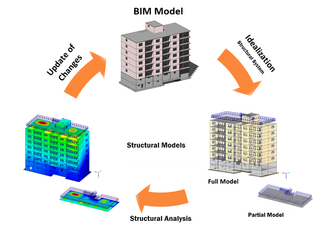
Building Information Modeling describes what is possibly one of the most important current topics in the entire construction software industry. However, the process is not that new, and it is a well-known fact that the total costs of a project can be positively influenced by good planning in the initial stage.
Modern buildings are designed with spaces tailored to personal desires and dreams, expressing individual lifestyles. These requirements often include ceilings - whether in houses, office buildings, or public buildings - that have an enormous span and no support, allowing optimal use of the space below. However, this requires a very high stability level for load‑bearing capacity and serviceability reasons. By extending the size of beam or plate cross-sections, you can increase the stability, but the cost effectiveness decreases because of the additional consumption of material. One common solution for these large spans is to use timber or steel downstand beams.